How to Find Standard Operating Temperature for Distribution Boards

Time:2026-10-13 Author:Mason
0%

Finding a safe operating temperature begins with a simple question: what is the standard operating temperature for electrical distribution boards? The answer is not one universal number. It depends on the board design, enclosure, connected load, ambient temperature, and manufacturer’s instructions. Many low-voltage assemblies are designed around an ambient temperature near 35°C, but this value should not be treated as a guaranteed internal temperature. The equipment documentation remains the controlling reference.

A reliable assessment combines field experience with recognized technical guidance. Standards such as IEC 61439 and NFPA 70 can support the evaluation, while a qualified electrician should interpret site-specific risks. Check the board when the building carries its normal load. Record the room temperature, circuit current, ventilation conditions, and visible signs of heat. A loose terminal may leave a darkened mark, brittle insulation, or a warm cable lug. Infrared scanning can reveal these patterns, but shiny metal surfaces may distort readings. Correct emissivity settings and comparison with similar connections matter.

Small details matter. Very much.

Temperature alone does not prove a fault. A warm breaker may reflect heavy demand, poor ventilation, an overloaded circuit, or an aging connection. It is also easy to trust one reading too quickly. Recheck unusual results, compare them with the manufacturer’s limits, and document changes over time. This approach produces evidence rather than guesswork. It also supports safer maintenance decisions, especially when distribution boards operate in hot plant rooms, dusty workshops, or tightly enclosed electrical cabinets.
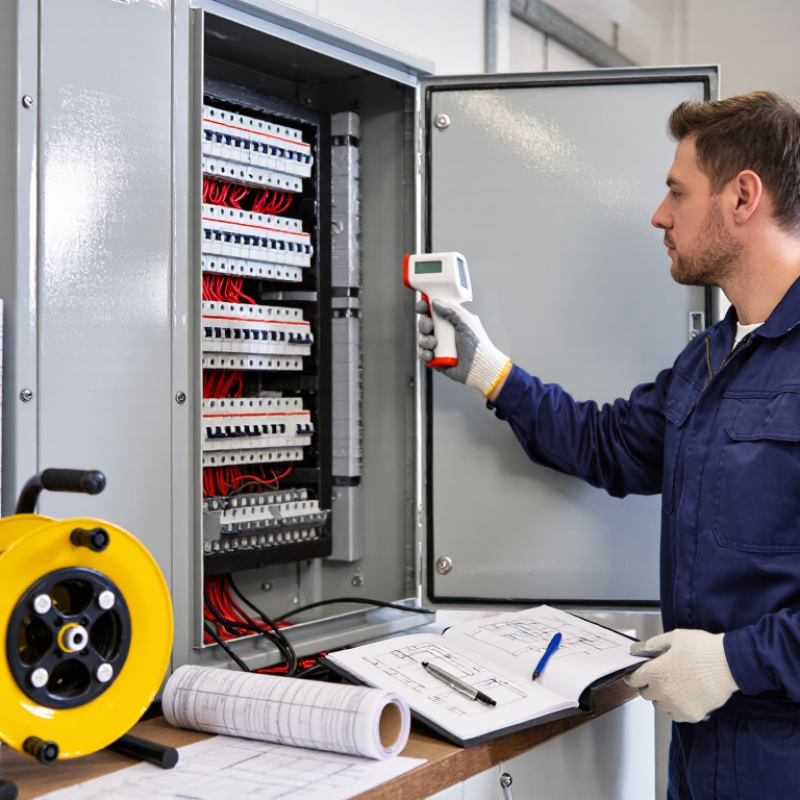
How to Find Standard Operating Temperature for Distribution Boards

Define the Operating Temperature of a Distribution Board

Defining the operating temperature of a distribution board requires more than reading its door surface. IEC 61439-1:2020 identifies normal ambient conditions as 40°C maximum, 35°C average over 24 hours, and -5°C minimum. These values describe the surrounding environment. They do not guarantee acceptable temperatures inside the enclosure. Busbars, terminals, breakers, and cables may run considerably hotter under load.

A practical definition combines ambient temperature, load current, and component temperature rise. Measure the room temperature beside the board, then record thermal images during peak demand. Check terminal connections, cable entry points, and busbar joints.

A cool enclosure can hide a hot terminal. NFPA 70B:2023 supports documented electrical preventive maintenance, including infrared inspection where appropriate. Compare readings with the component’s rated operating temperature and installation instructions.

Do not use one universal alarm limit. Cable size, enclosure ventilation, harmonics, and continuous loading change the result. A 38°C surface reading may be acceptable in one design and concerning in another.

I would not trust a single afternoon measurement. Repeat testing during seasonal peaks, after load changes, and following maintenance. Some uncertainty remains when emissivity is unknown. Clean reference points and calibrated instruments matter.

Identify Applicable Temperature Limits and Installation Standards

How to Find Standard Operating Temperature for Distribution Boards

Identify Applicable Temperature Limits and Installation Standards

A distribution board’s operating temperature depends on ambient heat, load, enclosure design, and installation conditions. IEC 61439-1:2020 uses 35°C as the maximum 24-hour average ambient temperature and 40°C as the usual maximum. Higher temperatures require verified derating or a tested assembly design. Do not treat 40°C as a guaranteed internal temperature. Busbars and terminals can run hotter.

NFPA 70, 2023 Edition, Section 110.14(C), links conductor termination limits to equipment ratings, conductor size, and installation conditions. Many terminations use 60°C or 75°C limits, but the equipment marking controls. IEC 60364-5-52 also requires correction factors for ambient temperature and grouped cables. These rules matter in crowded cabinets, rooftop rooms, and poorly ventilated electrical spaces. Field experience shows that loose terminations often create local hot spots before the room feels warm. That detail is easy to miss.

Tips: Record ambient and surface temperatures during peak load. Use calibrated thermal equipment, and compare each phase, neutral, and termination. Keep a load log. The hottest point may not be the busiest circuit. Review manufacturer test data and local code requirements before changing protection settings. Standards guide the decision, but site conditions can expose gaps. A first inspection may still be incomplete.

Measure Ambient and Internal Temperatures Under Normal Loads

How to Find Standard Operating Temperature for Distribution Boards

Measure ambient and internal temperatures while the distribution board carries its normal working load. A cold inspection can create false confidence. Record room temperature near the enclosure, away from vents, sunlight, and nearby heat sources. Then measure the enclosure surface at several points, including the top, sides, cable entries, and door.

Use a calibrated infrared thermometer, but check its limitations. Shiny metal can reflect nearby heat and produce unreliable readings. A contact probe can confirm suspicious results. If safe access is available, inspect internal connections with suitable electrical safety controls. Look for warmer breakers, terminals, busbar joints, and neutral connections. Small differences may be normal, but a sharp local rise deserves attention.

I prefer taking readings after the board has operated under a stable, representative load for at least one hour. Record the load, time, weather, ventilation condition, and each temperature. Compare the results with the equipment’s rated operating range and applicable electrical standards, not with a random online number. The acceptable limit depends on design, enclosure type, components, and ambient conditions. One inspection is not enough. Trends are more useful than isolated readings. I once trusted an infrared reading from a reflective cover; that shortcut was weak. Rechecking with a probe changed the assessment. A qualified professional should evaluate abnormal heating, especially near loose or discolored connections. Do not open an energized enclosure without proper training and controls.

How to Find Standard Operating Temperature for Distribution Boards

Ambient and internal temperatures measured under normal operating loads.

Internal temperatures are normally higher than surrounding ambient temperatures because of heat generated by conductors, terminals, and protective devices. These representative measurements remain below 45 °C internal temperature under normal loads. Actual operating limits should always be checked against the equipment rating, installation conditions, and applicable electrical standards.

Assess Heat Sources, Ventilation, and Load Distribution

How to Find Standard Operating Temperature for Distribution Boards

Assess Heat Sources, Ventilation, and Load Distribution

A distribution board has no universal operating temperature. Its acceptable range depends on enclosure design, components, ambient conditions, and manufacturer data. In field inspections, I begin by recording room temperature near the board. I then inspect terminals, breakers, busbars, and cable entries for concentrated heat. Nearby transformers, sunlight, and poorly tightened connections can raise temperatures unexpectedly.

Use an infrared camera during normal or peak loading conditions. Scan after the board has operated long enough to stabilize. Keep the viewing angle consistent. Reflective metal can distort readings. A contact thermometer can confirm suspicious hot spots. One reading is not enough. I once found a warm terminal that appeared harmless until phase current measurements showed a loose connection.

Ventilation needs equal attention. Check clearance around the enclosure, blocked louvers, dust on filters, and failed cooling fans. Enclosures installed in compact rooms may retain heat even when the board itself is correctly rated. Measure temperatures at the top, center, and bottom. Compare these results with the equipment’s documented limits, not with a convenient general rule.

Load distribution also affects operating temperature. Measure each phase and inspect neutral current, especially where nonlinear loads are present. Large differences between phases indicate imbalance and uneven heating. Redistributing circuits may reduce hot spots. However, this should follow a qualified assessment, because moving loads without reviewing protection settings can create new problems. Temperature logs across several days provide more reliable evidence than a single inspection.

Set the Standard Operating Temperature and Review It Regularly

To set a useful standard operating temperature, begin with the board’s documentation and the site’s normal conditions. Record ambient temperature, circuit load, enclosure type, and the hottest measured connection. Use a calibrated infrared camera or contact sensor after the board has carried a stable load. One brief reading is not enough. Repeat measurements at similar times, then establish an acceptable operating range rather than one rigid number. The equipment manufacturer’s limits and applicable electrical standards should guide the final threshold.

Review the standard whenever circuits are added, loads change, ventilation is blocked, or seasonal temperatures rise. Schedule checks after commissioning, planned maintenance, and complaints about heat, odor, or nuisance tripping. Compare each result with previous records. A rising trend often matters before an alarm appears. Pay close attention to uneven phases, loose terminations, discolored insulation, and warm cable entries. These details can reveal resistance or poor airflow. Keep the board closed during normal operation, and let qualified personnel investigate abnormal heat.

Temperature alone does not explain every problem. Ambient conditions, measurement angle, emissivity, and temporary load can distort the picture. The baseline may be imperfect at first. Review the method itself. Calibrate instruments, verify readings with a second method when practical, and update the baseline after repairs. Leave clear records of the date, load, location, weather, readings, and action taken. Good practice is repeatable, but never careless.

How to Find Standard Operating Temperature for Distribution Boards - Set the Standard Operating Temperature and Review It Regularly

Temperature Dimension Recommended Standard or Reference Point How to Measure Review Frequency Required Response
Ambient temperature around the board Target: 15–30°C
Preferred design limit: not more than 35°C average over 24 hours
Typical maximum reference condition: 40°C
Place a calibrated temperature sensor near the air inlet or at the front of the enclosure, away from direct heat sources. Continuous monitoring where possible; otherwise record monthly and during seasonal inspections. Investigate ventilation, room loading, solar gain, and nearby heat sources if the temperature exceeds 35°C.
Internal enclosure air temperature Set the site limit according to the enclosure, protective-device, and assembly ratings. A practical investigation threshold is 40°C internal air temperature. Measure at the warmest expected location inside the enclosure without touching energized parts. Quarterly and after changes in connected load or ventilation. Check derating requirements, airflow, enclosure spacing, and heat-producing equipment. Do not exceed the lowest rated component limit.
Breaker, fuse, and terminal surface temperature Use the component manufacturer's declared operating and terminal temperature limits. No universal surface-temperature value should replace the equipment rating. Use infrared thermography under representative load, correcting for emissivity and confirming abnormal readings with an appropriate contact method when safe. At least annually; also after overloads, protection trips, or maintenance work. Compare similar phases and adjacent devices. A localized or unbalanced hot spot requires an electrical connection and load investigation.
Temperature difference between phases Aim for balanced temperatures at comparable load. A difference above approximately 10°C should trigger investigation; confirm the limit in the site's maintenance procedure. Scan all phases at similar load and record load current with each temperature reading. During each thermographic inspection and after major load changes. Check phase loading, loose or corroded connections, conductor sizing, and harmonic current.
High-temperature alert level Set an alert when the measured temperature exceeds the approved normal operating range, commonly 35°C ambient or 40°C internal air, subject to the equipment rating. Use a permanently installed sensor or logged inspection readings. Review every monitoring cycle and after each alert. Verify load, airflow, enclosure condition, and sensor accuracy. Record the cause and corrective action.
Critical temperature level Critical level is reached when the lowest applicable equipment or assembly temperature rating is exceeded, or when rapid temperature rise indicates a fault. Confirm with an approved inspection method while observing electrical safety procedures. Immediate review when detected. Assess the risk, reduce or isolate the load if necessary, and arrange qualified electrical maintenance before returning to normal service.
Seasonal and operational review The approved operating-temperature standard should reflect the highest expected ambient temperature, maximum demand, enclosure arrangement, and component derating requirements. Review historical readings, peak-load measurements, inspection reports, and alarm records. At least annually; additionally after modifications, faults, relocation, or significant load growth. Update the site standard, alarm thresholds, inspection plan, and equipment derating assessment when conditions change.
Important note: Temperature limits must be verified against the applicable installation requirements, assembly design, protective-device ratings, enclosure specifications, and local electrical regulations. The lowest applicable rating always governs.

FAQS

What ambient temperature limits commonly apply to a distribution board?

A 35°C maximum 24-hour average is commonly used for ambient conditions. The usual maximum is 40°C. These values describe ambient air, not guaranteed internal temperatures. Higher temperatures may require verified derating or tested assembly data.

Does a 40°C room mean the distribution board is operating safely?

Not necessarily. Busbars, terminals, and cable connections can become much hotter than the room. Enclosure design, load, ventilation, and sunlight also affect internal heat. Measure actual conditions instead of assuming safety.

Which temperature limit applies to conductor terminations?

The equipment marking controls the permitted termination temperature. Many installations use 60°C or 75°C limits. Conductor size, equipment rating, and installation conditions also matter. Do not change protection settings using a general online number.

When should temperatures be measured?

Measure during normal operation after at least one stable hour. The board should carry a representative working load. Record the time, load, weather, ventilation, and measured temperatures. A cold inspection can create false confidence.

Where should enclosure temperatures be checked?

Measure near the room, away from vents, sunlight, and nearby heat sources. Check the enclosure top, sides, cable entries, and door. Also compare breakers, terminals, busbar joints, and neutral connections when safely accessible. The hottest point may not serve the busiest circuit.

Can an infrared thermometer provide reliable readings?

It can help, but shiny metal may reflect nearby heat. That reflection can produce a misleading result. Confirm suspicious readings with a suitable contact probe. I once trusted a reflective cover reading. That shortcut failed.

What temperature differences should raise concern?

Small differences may be normal between phases and components. A sharp local rise deserves investigation. Pay close attention to loose, discolored, or unusually warm connections. Compare each phase, neutral, and termination. Trends matter more.

What installation conditions can increase heating?

Crowded cabinets, grouped cables, rooftop rooms, and poor ventilation can raise temperatures. Cable grouping and ambient conditions may require correction factors. Loose terminations can create local hot spots before the room feels warm. That detail is easy to miss.

Is one temperature inspection enough?

No. Repeated readings reveal trends more clearly than isolated measurements. Keep a load log and compare similar operating conditions. A first inspection may remain incomplete. That is worth remembering.

What should happen when abnormal heating is found?

Compare readings with the equipment rating and applicable electrical standards. Review test data and site conditions before taking corrective action. A qualified professional should assess serious heating. Do not open an energized enclosure without proper training and controls.

Conclusion

Determining what is the standard operating temperature for electrical distribution boards requires more than choosing a single number. The operating temperature should be defined as the normal temperature range of the board and its components while carrying expected loads. Start by checking applicable electrical standards, equipment ratings, and installation requirements, then measure both the surrounding ambient temperature and internal hotspots during normal operation. Measurements should be taken under representative load conditions and repeated when practical to confirm consistent results.

A reliable assessment also considers heat-producing components, enclosure size, ventilation, nearby equipment, and how loads are distributed across circuits. Uneven loading or restricted airflow can create localized temperatures that are higher than the surrounding air. After reviewing these factors, set an operating temperature limit that remains within the ratings of all components and allows a suitable safety margin. Record the results, inspect connections regularly, and review the temperature standard whenever loads, ventilation, or installation conditions change.

Mason

Mason

Mason is a seasoned marketing professional with a deep expertise in the company's offerings and a passion for driving brand awareness. With a strong background in digital marketing strategies, he has an innate ability to connect with diverse audiences and effectively communicate product benefits.......