Harmonic distortion can quietly change how an industrial power distribution panel behaves. The panel may look normal, while current waveforms become uneven and stressed. Motors can run hotter. Transformers may produce an audible hum. Neutral conductors can carry unexpected current, even when phase loads appear balanced. Sensitive controls may also reset without a clear warning.
So, what causes harmonic distortion in industrial power distribution panels? The main sources are nonlinear loads, including variable frequency drives, switch-mode power supplies, LED lighting, battery chargers, and data equipment. These devices draw current in pulses instead of smooth sine waves. Their combined effect can increase voltage distortion throughout the panel. Poorly sized conductors, overloaded transformers, and weak upstream supplies may make the problem worse. Resonance with power factor correction capacitors is another serious concern.
The panel tells a story.
Reliable evaluation requires more than checking voltage with a standard multimeter. Qualified technicians normally use power quality analyzers to record total harmonic distortion, individual harmonic orders, neutral current, temperature, and load changes. Measurements should cover different operating conditions, because distortion may appear only when production equipment starts. IEEE 519 and relevant IEC practices can provide useful reference points, but site conditions still matter. A single reading never explains everything. Installation history, equipment age, maintenance quality, and future expansion should also be reviewed. Some assumptions may prove wrong. That is why experienced engineers compare measurements, drawings, and operating records before recommending filters, detuning reactors, or equipment changes.
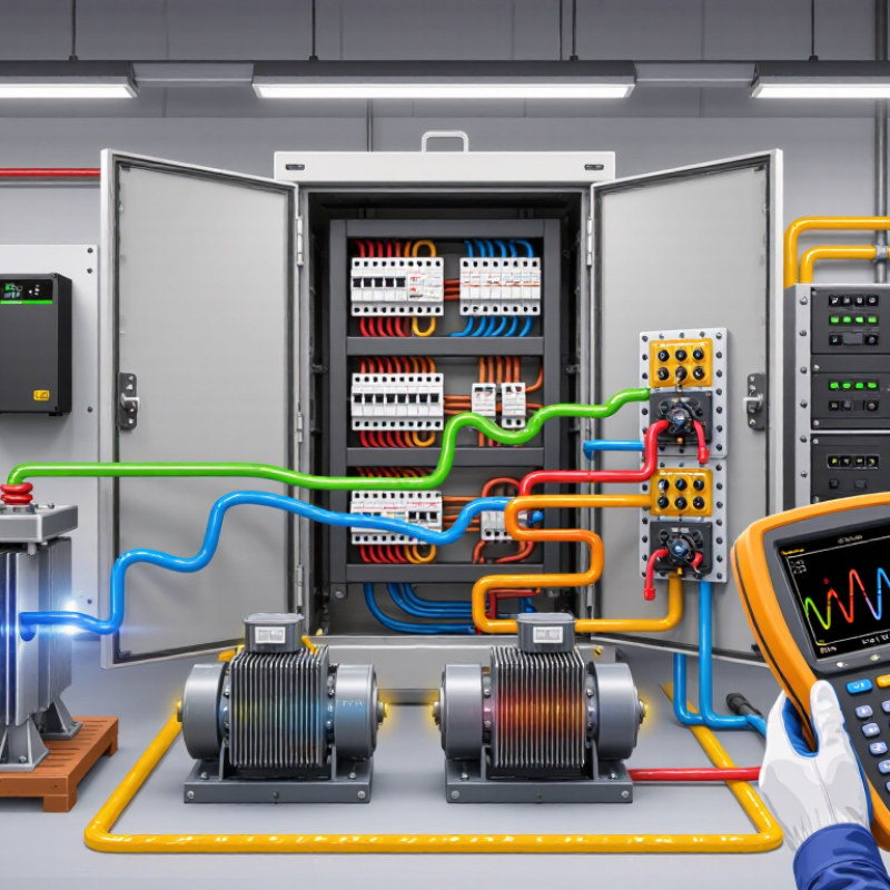
Harmonic distortion describes voltage or current waveforms that are no longer clean sine waves. In industrial systems, nonlinear loads create these unwanted frequencies. Common sources include variable-speed drives, rectifiers, uninterruptible power supplies, welding equipment, and switching power supplies. They draw current in pulses rather than smooth waves. The result is electrical stress inside the panel.
The effects can be very practical. Busbars and cable connections may run hotter than expected. Transformers can produce an audible hum. Protective devices may trip without an obvious short circuit. Neutral conductors are especially vulnerable because third-order harmonics can accumulate there. Sensitive control equipment may also experience unstable readings or unexplained resets. Small changes matter.
A proper assessment requires more than checking the panel temperature. Technicians should measure total harmonic distortion, individual harmonic orders, current levels, voltage quality, and load conditions. Measurements should be taken during production, not only during a quiet shift. A single snapshot can mislead. In field inspections, loose terminations sometimes appear to be the problem, while distorted current is increasing heat upstream. Filtering may help, but it should follow a study of system impedance and load behavior. Poorly selected correction equipment can create new resonance risks. Engineers should compare results with applicable electrical standards and equipment limits, then document readings over time. The analysis may still need revision when production changes.
Harmonic distortion begins when nonlinear equipment inside an industrial panel draws current in short, uneven pulses. Variable-speed drives, rectifiers, LED power supplies, and switching converters can create currents at multiples of the fundamental frequency. These currents travel through conductors, busbars, and transformers. Panel impedance then converts part of that current into unwanted voltage distortion. The waveform becomes less smooth.
The effects can appear gradually. Terminals may feel warmer than expected, neutral conductors can carry excessive current, and capacitors may overheat or interact with system resonance. Protective devices might trip without an obvious overload.
During field inspections, I have seen temperature patterns reveal problems before visible damage appeared. Still, one assumption needs caution. Heat is not always caused by harmonics. Loose connections, poor ventilation, and unbalanced loads can produce similar symptoms.
Tips: Measure current and voltage harmonics under normal operating conditions. Check neutral loading, transformer temperature, and capacitor behavior. Compare readings during production and idle periods. A single measurement can mislead. Record operating conditions, because harmonic levels often change with equipment speed and load. Review panel design, conductor sizing, and grounding practices with a qualified electrical professional. Small distortions may be acceptable, but rising values deserve investigation.
Harmonic distortion affects industrial panels because non-linear loads draw current in uneven pulses. Variable-speed drives, switching power supplies, and LED systems can create these current patterns. The result is higher RMS current, even when the measured load seems acceptable. More current means more heat in busbars, terminals, breakers, and cable connections.
Heat often appears slowly. A terminal may feel normal during a short inspection, then reach unsafe temperatures after hours of operation. Harmonics also increase skin and proximity effects, forcing current toward conductor surfaces and nearby metalwork. Neutral conductors can suffer too, especially when third-order harmonics accumulate. Capacitors may experience additional electrical stress and premature failure. I once underestimated a panel temperature rise because the daytime load was low. The evening readings told a different story.
Tips: Use a power-quality analyzer to measure harmonic current and voltage, not only basic amperage. Compare thermal images across phases, terminals, and neutral conductors under normal operating conditions. Keep connections correctly tightened and inspect for discoloration, vibration, or insulation damage. Check capacitor compatibility before installation. Where distortion is persistent, review conductor sizing, panel ventilation, filtering, and equipment derating with a qualified electrical professional. Measurements matter. Assumptions can mislead.
Why Does Harmonic Distortion Affect Industrial Panels?
Harmonic distortion damages industrial panel components by creating heat, vibration, and unwanted current. Nonlinear loads, including variable-speed drives, switch-mode power supplies, and LED systems, draw current in pulses. These pulses can overload neutral conductors and raise temperatures inside compact enclosures.
The U.S. Department of Energy’s Motor Systems Market Assessment estimates that motor-driven equipment consumes about 69% of industrial electricity. When distortion enters these systems, panel breakers, busbars, terminals, and transformers face additional thermal stress. IEEE 519-2022 commonly references a 5% voltage THD planning limit for systems up to 1 kV. Exceeding that level may shorten insulation life and cause nuisance tripping.
The damage is often gradual.
Field inspections frequently find discolored terminals before a failure occurs. Infrared scans can reveal hot connections, but they cannot explain the complete cause. Engineers should measure voltage and current harmonics under normal and peak operating conditions. A panel may look clean and still run dangerously hot. This is where routine assumptions fail.
Tips: Check neutral current, transformer loading, and terminal torque during maintenance. Compare readings with IEEE 519-2022 limits and equipment specifications. Log temperature trends, not only alarm events. Also, review recently added loads; one new drive can change the panel’s harmonic profile significantly.
Harmonic current increases the total RMS current flowing through panel conductors, busbars, breakers, and connections. Because resistive heating is proportional to the square of RMS current, even moderate distortion can increase thermal stress and accelerate component aging.
The values are calculated from the relationship heating ratio = 1 + THDi², assuming harmonic current is expressed as a percentage of fundamental current and conductor resistance remains constant. For example, 20% THDi produces approximately 4% additional I²R heating before other effects such as skin effect, neutral-current accumulation, and resonance are considered.
Why Does Harmonic Distortion Affect Industrial Panels?
Methods for Measuring and Reducing Harmonic Distortion
Harmonic distortion begins when nonlinear loads draw current in uneven pulses. Variable-speed drives, switch-mode power supplies, and LED systems can create these pulses. The result is extra heating, nuisance tripping, and unstable readings inside industrial panels. Neutral conductors may also carry high third-harmonic current, even when phase currents appear balanced.
Measure at the panel. Use a power-quality analyzer to record voltage THD, current THD, individual harmonic orders, frequency, and load demand. A qualified technician should measure during normal production and peak operating periods. Take readings at the main incomer, major feeders, and sensitive equipment. Thermal imaging can reveal hot terminals or overloaded neutrals. Numbers can mislead. One short measurement may miss distortion that appears only during a production cycle.
Reducing distortion starts with a load survey and accurate documentation. Balance single-phase loads across the phases, tighten connections safely, and separate sensitive circuits from heavy nonlinear equipment. Line reactors, passive filters, or active harmonic filters may help, but each solution requires system calculations. A filter installed without checking resonance can create new problems. I have seen panels cool after filtering, yet a loose neutral remained unnoticed. Retest after every major change, compare results with applicable electrical standards, and keep dated records for future maintenance. Industry conditions change, so an old measurement may not describe today’s panel.
| Data Dimension | Parameter | Typical or Reference Data | Effect on Industrial Panels | Measurement Method | Practical Reduction Method |
|---|---|---|---|---|---|
| Distortion Indicator | Voltage THD | Percentage of the RMS voltage contributed by harmonic components. A commonly used planning value at a point of common coupling for systems rated up to 1 kV is 5% total voltage distortion. | Can cause overheating, control malfunctions, nuisance trips, transformer noise, and inaccurate operation of sensitive equipment. | Use a power-quality analyzer at the panel main bus and compare readings during minimum, normal, and maximum loading. | Reduce current harmonics at the source, install tuned or active filters, increase system impedance where appropriate, and separate sensitive loads from high-distortion loads. |
| Distortion Indicator | Current THD | Ratio of harmonic current to the fundamental current. The acceptable level depends on the short-circuit ratio, load current, system voltage, and harmonic order. | Increases conductor and breaker heating, reduces usable capacity, and may overload neutral conductors. | Measure phase current and harmonic spectrum with a true-RMS instrument using appropriately rated current probes or flexible sensors. | Use lower-distortion rectifiers, line reactors, passive filters, active harmonic filters, or multipulse converter arrangements. |
| Dominant Harmonics | 5th and 7th harmonics | Common in six-pulse power converters and many variable-speed drive input sections. The 5th is a negative-sequence component; the 7th is a positive-sequence component. | May produce motor torque pulsation, additional heating, vibration, transformer losses, and voltage waveform distortion. | Review individual harmonic magnitude and phase angle rather than relying only on the total THD value. | Apply tuned filters designed for the actual system impedance, or use active filters and higher-pulse conversion equipment. |
| Neutral Loading | Triplen harmonics: 3rd, 9th, 15th and higher multiples of three | In balanced three-phase four-wire systems, zero-sequence triplen currents can add in the neutral instead of canceling. | The neutral conductor can become heavily loaded even when phase currents appear balanced, increasing heat and fire risk. | Measure each phase and the neutral simultaneously under representative operating conditions. | Use correctly sized neutral conductors, harmonic-mitigating transformers, zero-sequence filters, and low-distortion power supplies. |
| Thermal Stress | Additional RMS heating | RMS current includes the fundamental and harmonic components: IRMS = √(I12 + I22 + I32 + …). | Raises I²R losses in busbars, cables, breakers, transformers, terminals, and contactors. | Combine electrical measurements with infrared inspection of bus joints, terminals, breakers, and cable connections. | Correct loose connections, verify thermal ratings, redistribute loads, improve ventilation, and reduce harmonic current at the source. |
| Power Factor | True power factor | True power factor includes both displacement and distortion effects. It is lower than displacement power factor when harmonic current is present. | Increases apparent power demand, reduces available panel capacity, and may increase utility charges where applicable. | Record kW, kVA, kVAR, displacement power factor, true power factor, voltage THD, and current THD together. | Do not add conventional capacitor correction without a resonance study; use detuned banks or active solutions when harmonics are significant. |
| Resonance Risk | Capacitor-bank interaction | Power-factor capacitors can create parallel or series resonance near a harmonic frequency, depending on system inductance and capacitance. | Can amplify voltage or current distortion, causing capacitor overheating, fuse operation, and equipment failure. | Measure harmonics with capacitors switched in and out, and perform an impedance or resonance study for the complete system. | Use detuned reactors, properly designed passive filters, or active harmonic filters; confirm tuning against the actual network impedance. |
| Measurement Setup | Sampling location and duration | Measure at the panel incomer, major nonlinear-load feeders, and the point of common coupling. Capture start-up, steady-state, peak-load, and lightly loaded periods. | A short measurement at one operating point may miss intermittent distortion and load-dependent resonance. | Use a power-quality analyzer capable of recording waveform, RMS values, individual harmonics, THD, events, and trends. | Create a baseline before modifications and repeat the same measurement points and operating conditions after corrective work. |
| Common Sources | Nonlinear electrical loads | Typical sources include variable-speed drives, switch-mode power supplies, uninterruptible power systems, battery chargers, arc equipment, and LED drivers. | Multiple sources can interact, making the panel waveform more distorted than any single branch circuit suggests. | Survey feeder currents and compare each load’s harmonic spectrum with the total panel spectrum. | Specify low-harmonic equipment, add input reactors or DC chokes where suitable, and segregate high-distortion feeders. |
| Verification | Post-correction performance | Confirm lower voltage and current distortion, acceptable temperatures, stable power factor, and no new resonance or nuisance tripping. | A filter that reduces one harmonic can unintentionally increase another if it is not coordinated with the network. | Repeat trend measurements and inspect thermal conditions under the same or higher representative load. | Document baseline and final values, review protection settings, and schedule periodic power-quality checks. |
Harmonic distortion occurs when voltage or current stops following a clean sine wave. Nonlinear loads create pulsed current. Small pulses can create large heating problems.
Variable-speed drives, rectifiers, backup power units, welding equipment, and switching supplies can produce distortion. Lighting systems may contribute too. One new drive can change the panel’s behavior.
It creates extra heat, vibration, and unwanted current. Busbars, terminals, transformers, and breakers may operate above normal temperatures. Damage often develops gradually.
Third-order harmonics can accumulate in the neutral conductor. The phase currents may appear balanced, yet the neutral can become overloaded. That detail is easy to miss.
Watch for hot terminals, discolored connections, transformer hum, nuisance trips, unstable readings, and unexplained equipment resets. A clean-looking panel can still run dangerously hot.
Use a power-quality analyzer during normal production and peak operating periods. Record voltage distortion, current distortion, individual harmonic orders, frequency, and load demand.
Usually not. Distortion may appear only during a production cycle. Measure the main incomer, major feeders, and sensitive equipment. One snapshot can mislead.
Review the loads, balance single-phase circuits, secure connections safely, and separate sensitive circuits from heavy nonlinear equipment. Reactors or filters may help. Test again afterward.
Yes. Poorly selected correction equipment can interact with system impedance and create resonance. Calculations should come before installation. Cooling alone does not prove the solution worked.
Keep dated readings for temperatures, neutral current, transformer loading, harmonic levels, and equipment changes. Recheck after major production changes. Old data may no longer describe the panel.
Harmonic distortion in industrial electrical systems occurs when nonlinear loads draw current in irregular pulses rather than smooth sine waves. This changes the quality of power circulating through industrial panels and can affect the performance of connected equipment. Common sources include variable-speed drives, switching power supplies, rectifiers, and other electronic loads. Understanding what causes harmonic distortion in industrial power distribution panels is essential for maintaining reliable and efficient operations.
As harmonic currents accumulate, they can increase heat in conductors, transformers, busbars, and neutral wiring while placing additional electrical stress on insulation and connections. Over time, this may contribute to nuisance tripping, inaccurate measurements, premature component aging, and unexpected equipment downtime. Engineers can assess the problem by using power-quality analyzers, waveform monitoring, and thermal inspections. Mitigation methods may include load balancing, properly sized conductors, harmonic filters, improved system design, and regular maintenance. Managing distortion helps protect panel components, reduce energy losses, and support safer, more stable industrial power distribution.

Sowest Electric