Choosing DC screen capacity for a substation is not just a matter of matching a panel to the battery voltage. The screen must support protection, control, signaling, communications, and other essential DC loads without being undersized. The right choice depends on the actual duty of the installation. Small details matter. A trip coil that operates briefly and a continuously energized relay do not place the same demand on the system.
This guide explains how to choose the right dc screen capacity for substations through five practical checks. It looks at connected loads, continuous and momentary demand, spare feeder ways, fault ratings, and coordination with the battery and charger. Start with verified drawings and equipment data, then check whether the listed loads reflect real operating conditions. A feeder schedule can look complete while missing a recently added communication device. That happens, and it deserves a second look. Allowing reasonable room for future circuits can help, but excessive spare capacity may increase cost without improving reliability.
The five tips provide a structured starting point, not a substitute for a project-specific engineering review. Confirm voltage, load assumptions, breaker ratings, and applicable utility requirements before final selection. Where duty cycles or operating scenarios are unclear, document the uncertainty and seek qualified review. Capacity is important, but so are sound protection and clear records.
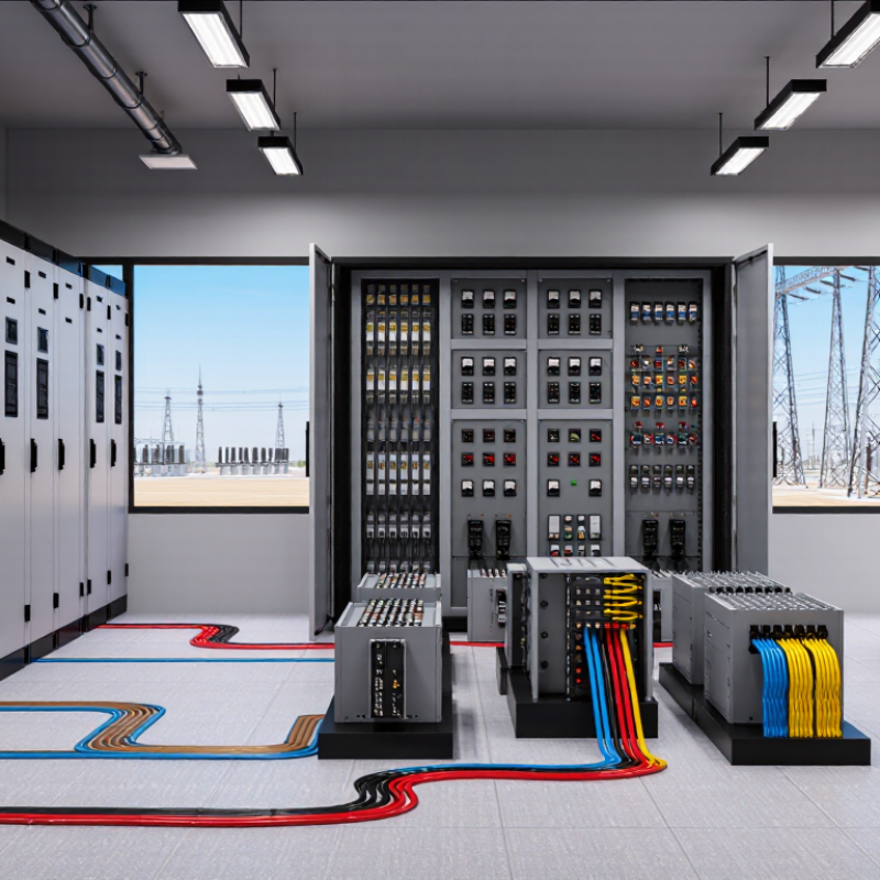
Begin with a load inventory, not a battery estimate. List continuous loads such as protection relays, control circuits, communications equipment, and indication lamps. Record each load’s normal current and operating voltage. Small loads add up, especially when several panels share one DC system. Check actual equipment data where available; old drawings may not reflect later changes.
Next, map the full duty cycle in time order. Include a trip-coil operation, breaker-failure protection, alarms, and any closing-coil operation required after a fault. Note each event’s current, duration, and likely overlap with other loads. Continuous demand draws energy steadily; trip and closing loads create short, high-current pulses. Both matter. A battery may have adequate ampere-hour capacity yet struggle with voltage drop during a coil operation.
Use the inventory to model realistic and demanding sequences, including control-room actions and protection responses that can occur together. Check cable and connection resistance, minimum battery voltage, temperature, and aging assumptions. Then verify the design against equipment limits and applicable engineering requirements. A spreadsheet can look precise while hiding an overlooked load. Walk the panels, compare labels with records, and revise the duty cycle when site conditions disagree. The disagreement is useful.
Choosing nominal DC bus voltage is an early design decision, not a label added after sizing. Substations commonly use 48, 125, or 250 VDC, but the right choice depends on relay, breaker-trip, control, and communications loads. Check every device nameplate and the station’s existing DC architecture. Small details matter. A trip coil may tolerate a narrow voltage range, while long cable runs reduce voltage at the far end.
At 48 VDC, lower-voltage equipment can be convenient, yet current rises for the same power. That can mean larger conductors and closer attention to voltage drop. A 125 VDC bus is common for protection and control circuits in many substations, offering a practical balance between equipment availability and wiring demands. Still, “common” does not mean correct. Verify the minimum voltage at each critical load during battery discharge, including simultaneous breaker operation.
A 250 VDC system may suit stations with compatible trip and control equipment, but it requires insulation ratings and maintenance procedures suited to the higher voltage. Compare charger and battery options, existing panels, cable lengths, and future expansion before committing. Write down the assumptions. They are easy to forget. Do not select voltage by capacity alone: nominal voltage determines system compatibility, while ampere-hour capacity must cover the required duty cycle and autonomy. Have the design checked against equipment specifications and site conditions; real installations rarely match a tidy spreadsheet exactly.
Compare the nominal bus options, then size the battery in ampere-hours from the station’s load and required duty cycle.
| Selection factor | 48 VDC | 125 VDC | 250 VDC |
|---|---|---|---|
| Typical applications | Communications, networking, and lower-voltage control loads | Common substation control, protection, and breaker-trip loads | Higher-voltage control and protection systems where specified by the design |
| Example lead-acid string | 24 cells in series, using 2 V nominal cells | 60 cells in series, using 2 V nominal cells | 120 cells in series, using 2 V nominal cells |
| Illustrative float-voltage range | 52.8–54.0 V | 132–135 V | 264–270 V |
| Voltage-range basis | Illustrative values use 2.20–2.25 V per lead-acid cell at float. Confirm the permitted charging and load-voltage limits against the selected battery and connected equipment. | ||
| Capacity sizing input | Determine battery ampere-hours from the continuous load, intermittent loads, required autonomy, end-of-discharge voltage, temperature, aging, and the specified breaker-trip or switching duty cycle. Voltage alone does not determine capacity. | ||
| Key selection check | Verify that connected devices support the bus’s normal and charging voltages; consider voltage drop on longer cable runs. | Check relay, trip-coil, and control-device voltage limits at both the highest charging voltage and the lowest discharge voltage. | Confirm equipment insulation and voltage ratings, protection coordination, and safe maintenance procedures for the higher DC voltage. |
| Practical tip | Use the site’s load list and required outage duration to calculate battery capacity, then verify charger output, redundancy, and future load allowance. | ||
Note: Applications and voltage values are indicative. Final design should follow project requirements, applicable standards, and the battery manufacturer’s data.
A dependable DC screen starts with a dependable duty cycle. IEEE 485 provides a method for sizing stationary lead-acid batteries against the loads they must support. List each load, its current, and how long it operates. Include continuous relays, breaker trips, alarms, and short-duration switching loads. Small loads matter.
Arrange the loads in time order, from normal operation through the worst credible outage sequence. The battery must supply the combined demand at each point, while staying above the equipment’s minimum DC voltage. Do not simply add every load’s ampere-hours and treat that as the final capacity. Discharge rate and cell performance affect what capacity is available.
Apply the relevant temperature and aging factors, then check the selected battery against the full duty cycle and project requirements. Keep the assumptions visible: a trip coil listed as a brief pulse can be missed or assigned the wrong duration. One weak spot is often the load list, not the arithmetic. A spreadsheet can look precise while its inputs remain uncertain. Have protection and operations staff review unusual sequences before approving the capacity.
A substation battery must carry its defined duty cycle, not just the steady control-room load. List each load and its duration, including breaker trips, alarms, and emergency lighting. Add the demands across the required discharge period, then apply the IEEE 485 aging factor of 1.25 to account for capacity loss over service life. This is a design allowance, not a substitute for a clear load schedule. Small omissions matter.
Tip: Correct for the coldest expected battery temperature. Low temperatures reduce available capacity, so use the temperature correction method and data specified by the applicable IEEE 485 edition and battery documentation. Check the actual battery-room conditions, including ventilation and seasonal extremes. A room that is usually warm may still become cold during an outage. Cold changes everything.
Tip: Keep the factors visible in your calculation. Show the duty-cycle result, aging allowance, temperature correction, and selected standard battery size separately. This makes review easier and helps prevent applying the same margin twice. I would also document assumptions about future loads; they are often less certain than the arithmetic. Have the final sizing checked against site requirements and the manufacturer’s discharge data before procurement.
Choosing DC screen capacity starts with the load schedule, not the charger nameplate. IEEE 946-2020 recommends evaluating the DC system as a whole: loads, battery, charger, distribution, and voltage limits. List continuous loads such as protection relays and control circuits, then identify brief peaks from breaker trip coils. Separate them carefully. Their durations differ.
Use a traceable calculation. For an illustrative 125 V station, a 12 A continuous load plus an 8 A battery-recharge allowance means the charger must supply at least 20 A before design margins. This equals 2.5 kW at nominal voltage. It is an example, not a universal rating.
IEEE 485-2020 provides methods for sizing stationary lead-acid batteries against duty cycles; apply its approach to the actual sequence of trips, alarms, and outages. That assumption can fail if several breakers operate together.
Check performance at the battery’s minimum voltage, not only at nominal voltage. Record cable lengths, connection resistance, and the voltage at the farthest relay panel during a trip test. Compare charger output, battery duty, and allowable load voltage against IEEE 946. Keep the test results with the load schedule. Small omissions matter. A charger can meet its ampere rating yet leave remote devices below their operating limits. Revisit the figures after protection changes or added communications equipment.
List continuous loads such as protection relays, control circuits, communications equipment, and indication lamps. Include their normal current and operating voltage. Small loads add up.
It shows how loads occur over time, including trips, alarms, and closing operations. Some events may overlap. A brief coil pulse can demand high current.
No. Discharge rate and cell performance affect available capacity. Check that the battery supports the entire sequence while maintaining minimum equipment voltage.
Record each event’s current, duration, and likely overlap with other loads. Check equipment data and site labels. Old drawings may be wrong.
Apply the IEEE 485 aging factor of 1.25 to account for capacity loss over the battery’s service life. Keep this factor visible in the calculation.
Cold reduces available capacity. Use the temperature correction method and data specified by the applicable standard and battery documentation. Check seasonal room conditions.
Review the load list, event durations, cable resistance, minimum voltage, temperature, and aging assumptions. Protection and operations staff can help identify unusual sequences. Some inputs remain uncertain.
Show the duty-cycle result, aging allowance, temperature correction, and selected battery size separately. Compare the result with equipment limits and discharge data. Check it again.
Choosing the right DC screen capacity for a substation starts with understanding every load the system must support. List continuous loads, such as control and protection equipment, alongside momentary trip and closing loads. Consider when each load operates and how long it must be supplied during the complete duty cycle. Then select a nominal bus voltage—commonly 48, 125, or 250 VDC—based on the substation’s equipment and system requirements. This load and voltage assessment provides the foundation for how to choose the right dc screen capacity for substations.
Calculate the required battery capacity from the duty cycle using IEEE 485, then apply the standard’s 1.25 aging factor and account for the effects of the minimum expected temperature. Capacity alone is not enough: check that the charger can support the connected loads and recharge the battery as required. Finally, assess the overall DC system’s performance against IEEE 946 to confirm that the selected capacity and supporting equipment meet the substation’s needs.

Sowest Electric