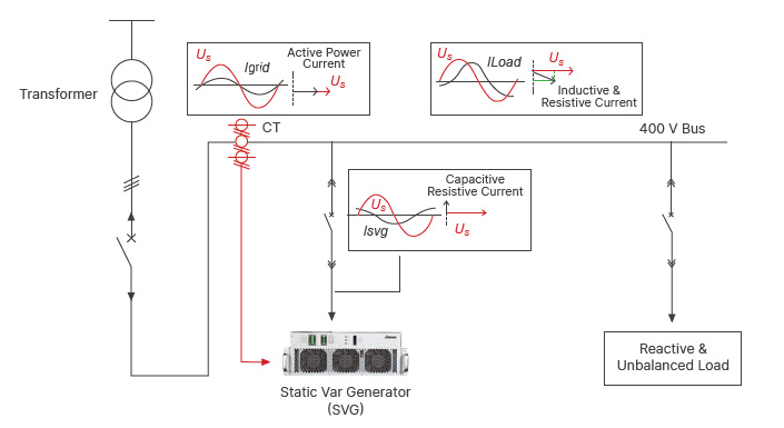
Working Principle
The principle of the SVG is very similar to that of Active Power Filter. When the load is generating inductive or capacitive current, it makes load current lagging or leading the voltage. SVG detects the phase angle difference and generates leading or lagging current into the grid, making the phase angle of current almost the same as that of voltage on the transformer side, which means fundamental power factor is unit. SVG is also capable of correcting load imbalance.
Feature
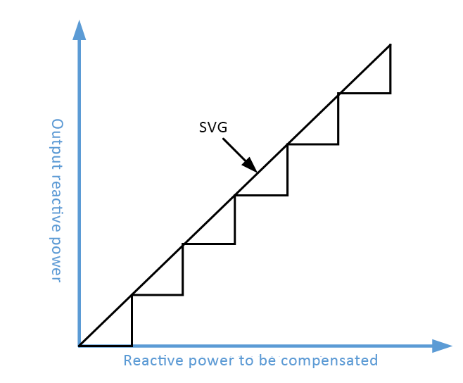
Continuous Compensation: It can realize continuous and accurate compensation of inductive and capacitive reactive power.
Harmonic Elimination: SVG can eliminate the odd harmonics in the output current by multiple, multilevel or cascade technology, so that its output waveform is closer to sine wave.
Current harmonic content < 2.5%
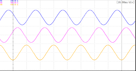
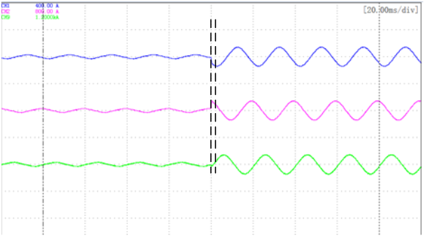
Fast Response: SVG based on PWM technology can respond quickly within half a power frequency cycle, and the response time can reach less than 10ms.
SVG Step current waveform (response time < 3ms)
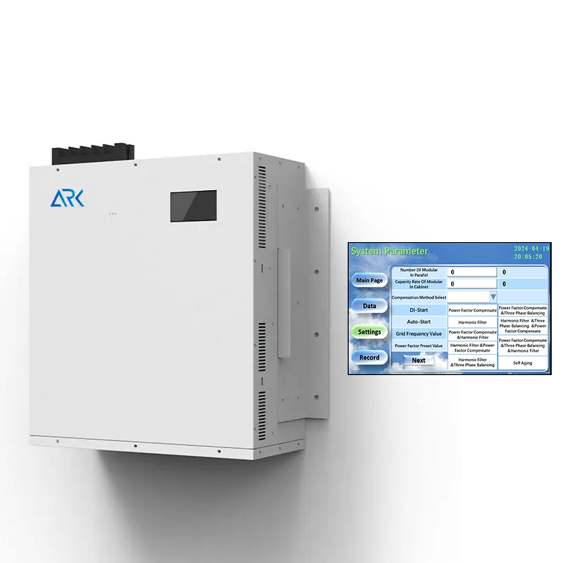
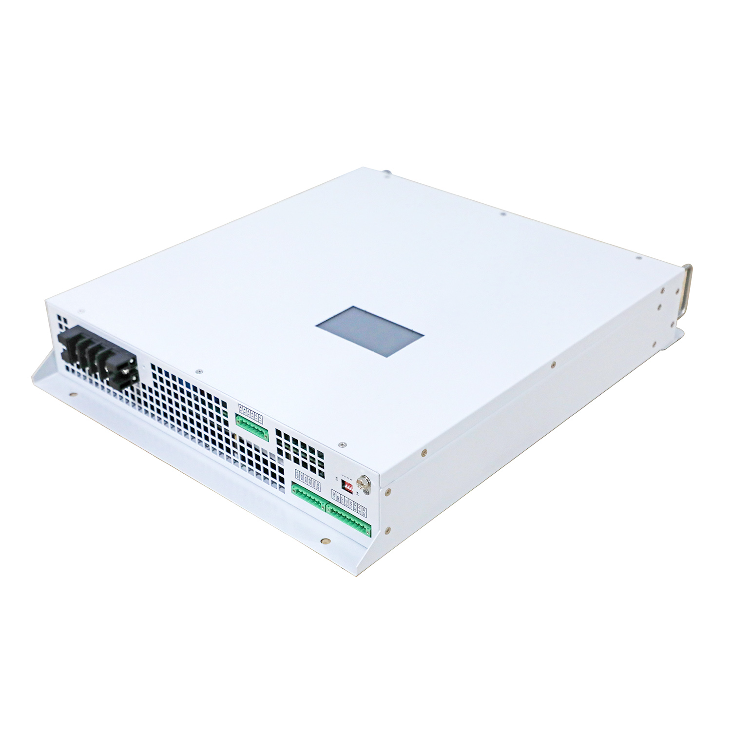
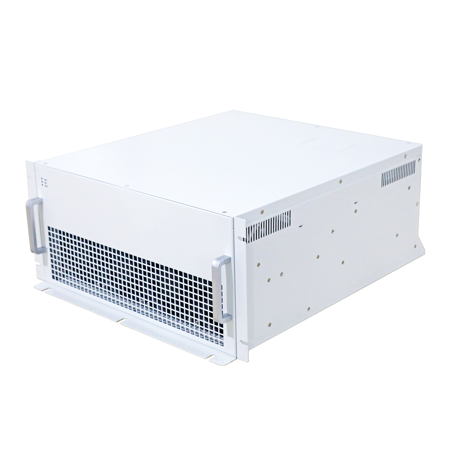
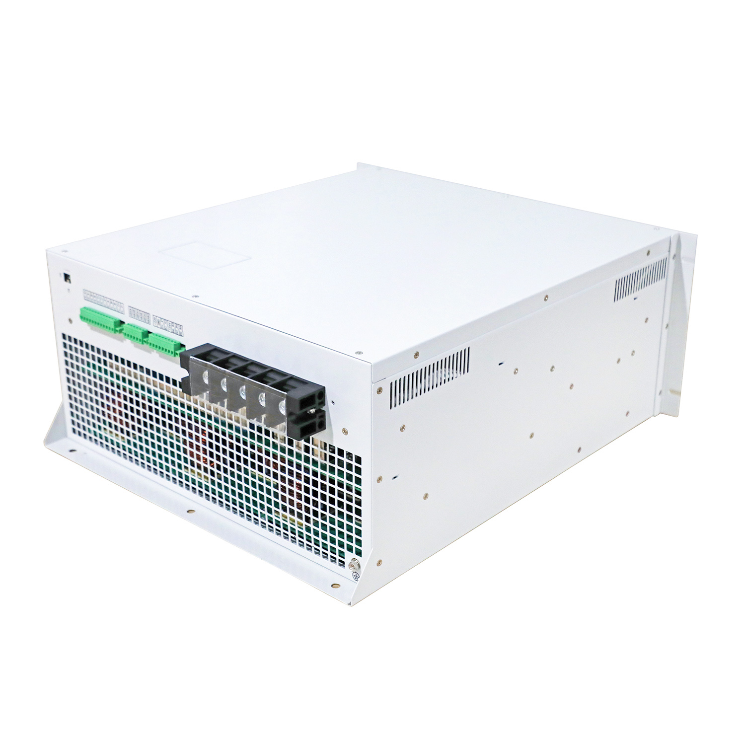
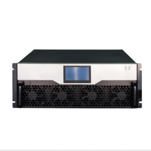
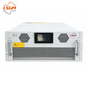
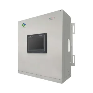
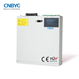
Products Description
★ OUTSTANDING PERFORMANCE
- Reactive power compensation > 99%
- Continuous correction – step less control. SVG controls from 0 – rated kVAr as one continuous range. Think of it like a power factor VSD.
- Capacitive and Inductive compensation: -1 to +1.
- 50µs response time with full correction in less than 15ms. Suitable for highly dynamic loads where the power factor fluctuates rapidly or in big steps e.g. saw mills, cranes, welders.
- No over compensation or under compensation as experienced with capacitor switching systems.
- Current imbalance correction can correct for load imbalance across all three phases.
🛡 NETWORK FRIENDLY AND HIGHLY STABLE
Unlike traditional capacitor based systems, the SVG does not negatively interact with your electrical system. Today’s harmonically rich environments are tough on capacitor based systems with increased risks of resonance and capacitor failures.
- Unaffected by harmonic distortion and free from harmonic resonance.
- Unaffected by network voltage drop. Even under reduced network voltage levels full reactive current can be provided to meet working conditions.
- There is no nasty transient voltage spikes caused by the switching of capacitors.
- Presents to the electricity grid as a very high impedance device. Network companies need not worry about the attenuation of ripple injection signals.
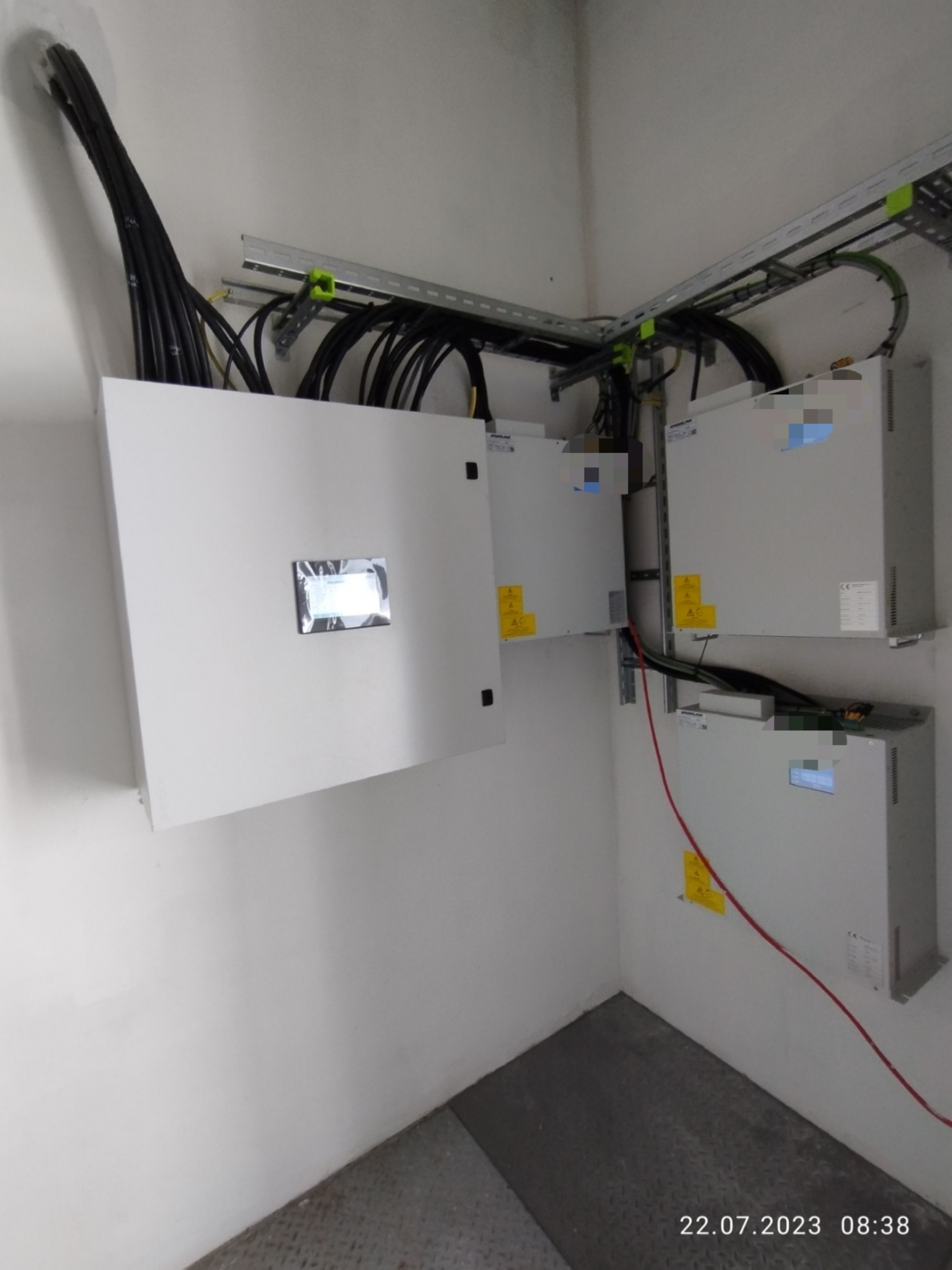
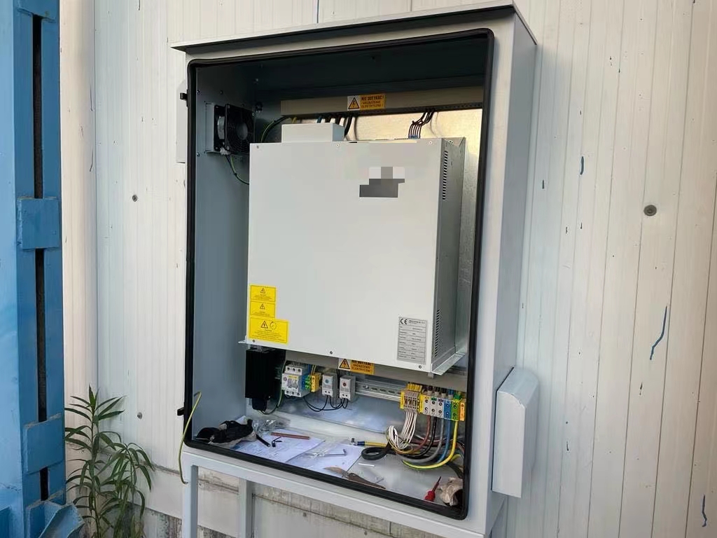
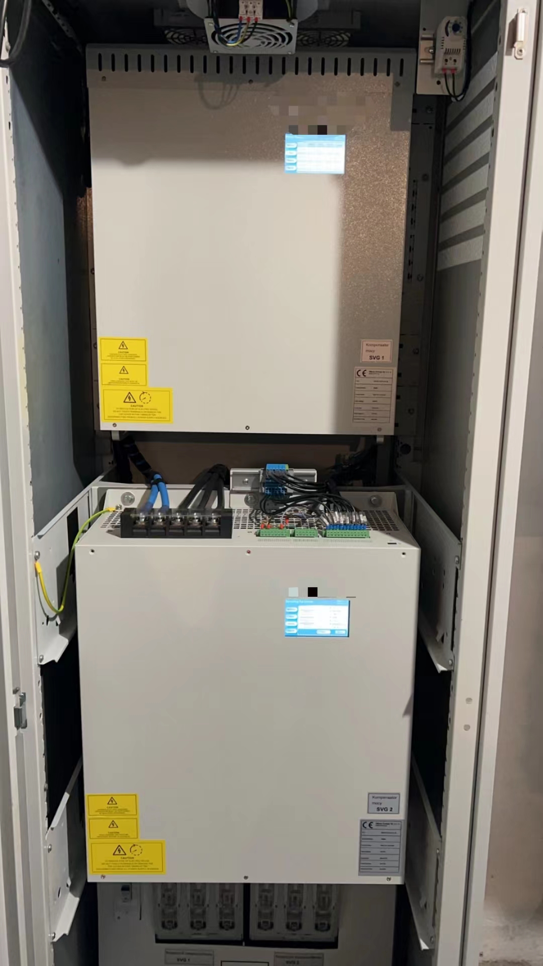
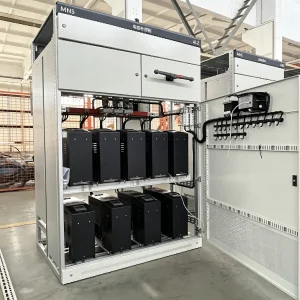
Project Case
Manufacturing Shop
Product Parameters
| Type |
Series 220V |
Series 400V |
Series 500V |
Series 690V |
| Max neutral wire current |
5KVar |
10KVar/15KVar/35KVar/50KVar/75KVar/100KVar |
90KVar |
120KVar |
| Nominal voltage |
AC220V (-20%~+20%) |
AC380V (-20%~+20%) |
AC500V (-20%~+20%) |
AC690V (-20%~+20%) |
| Rated frequency |
50Hz ± 5% |
| Network |
Single phase |
Three-phase three-wire / Three-phase four-wire |
| Response time |
< 10ms |
| Reactive power compensation rate |
> 95% |
| Machine efficiency |
> 97% |
| Switching frequency |
32kHz |
16kHz |
12.8kHz |
12.8kHz |
| Feature selection |
Deal with harmonics / Deal with harmonics and reactive power |
Deal with harmonics / Deal with harmonics and reactive power / Deal with harmonics and three-phase unbalance (Three options) |
| Numbers in parallel |
No limitation. A single centralized monitoring module can be equipped with up to 8 power modules. |
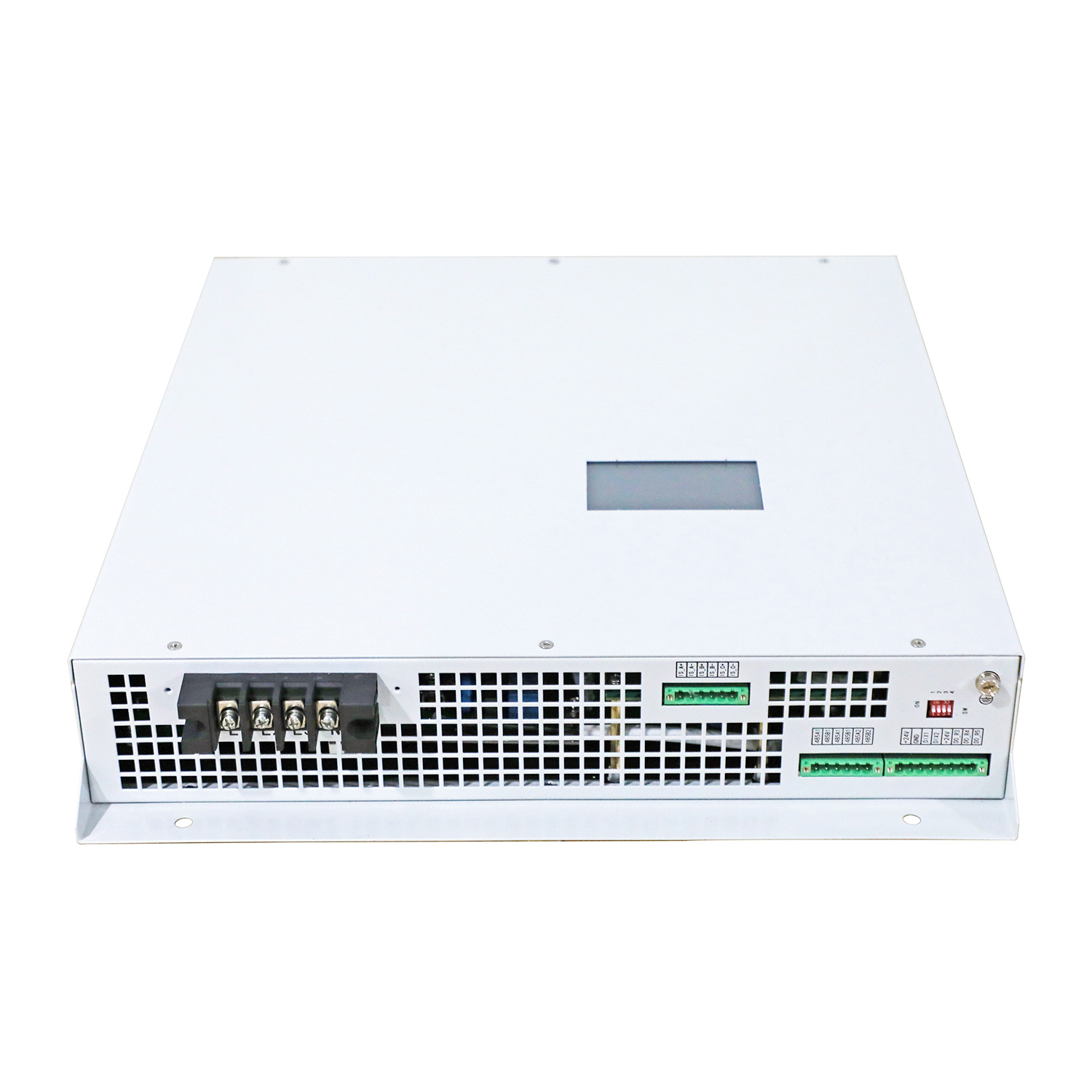
| Communication methods |
Two-channel RS485 communication interface (support GPRS/WIFI wireless communication) |
| Altitude without derating |
< 2000m |
| Temperature |
-20 ~ +50°C |
| Humidity |
--- |
| Pollution level |
Below level Ⅲ |
| Protection function |
Overload protection, hardware over-current protection, over-voltage protection, power grid voltage imbalance protection, power failure protection, over-temperature protection, frequency anomaly protection, short circuit protection, etc. |
| Noise |
< 50dB |
< 60dB |
< 65dB |
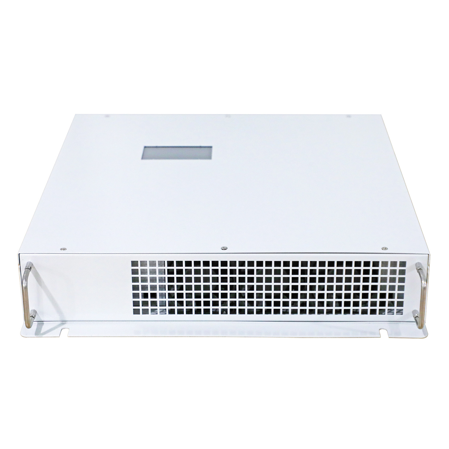
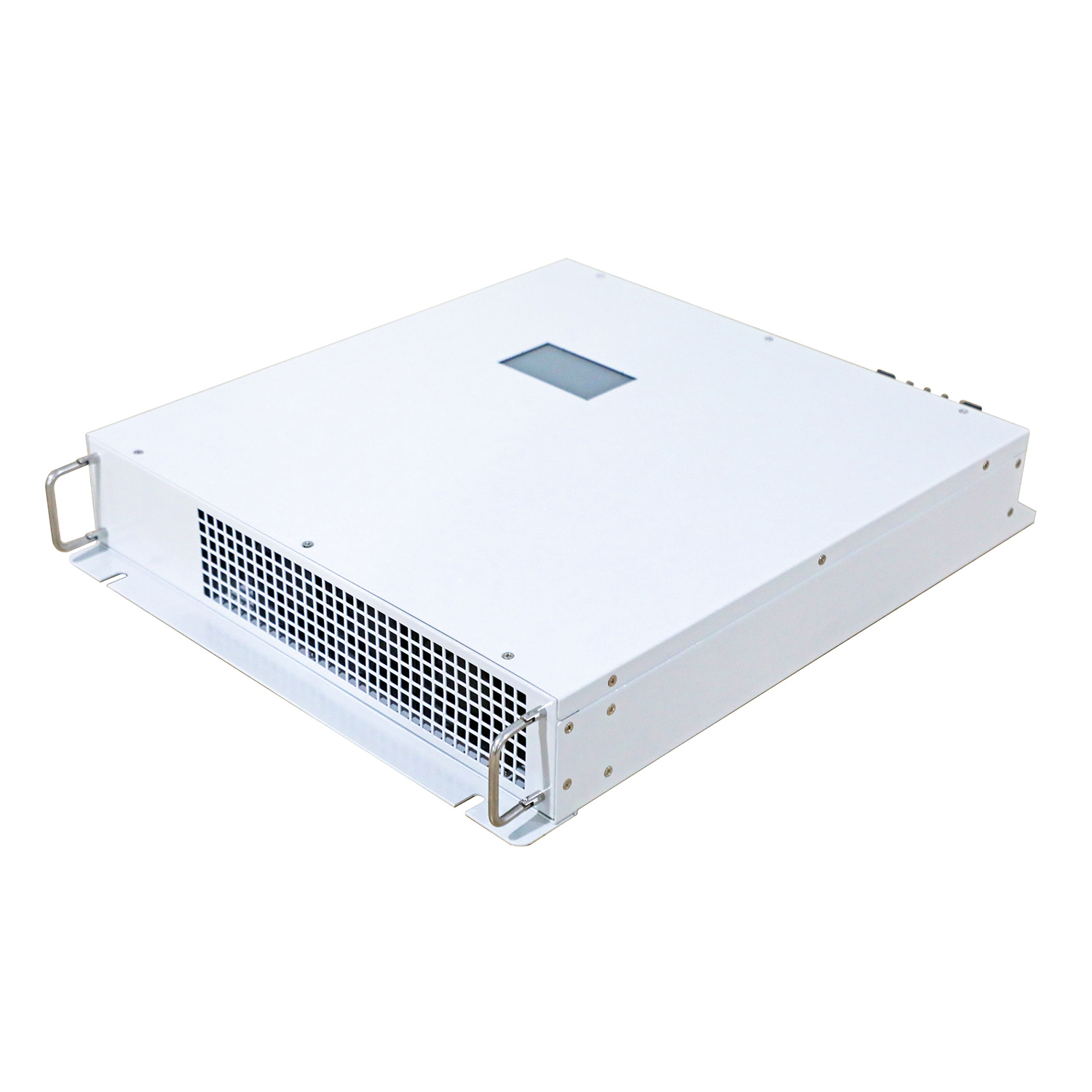
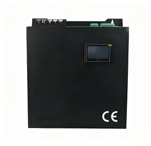
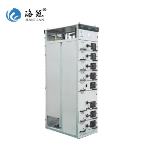
| Installation |
Rack/wall hanging |
Rack |
| Into the way of line |
Back entry (rack type), top entry (wall-mounted) |
Top entry |
| Protection grade |
IP20 |
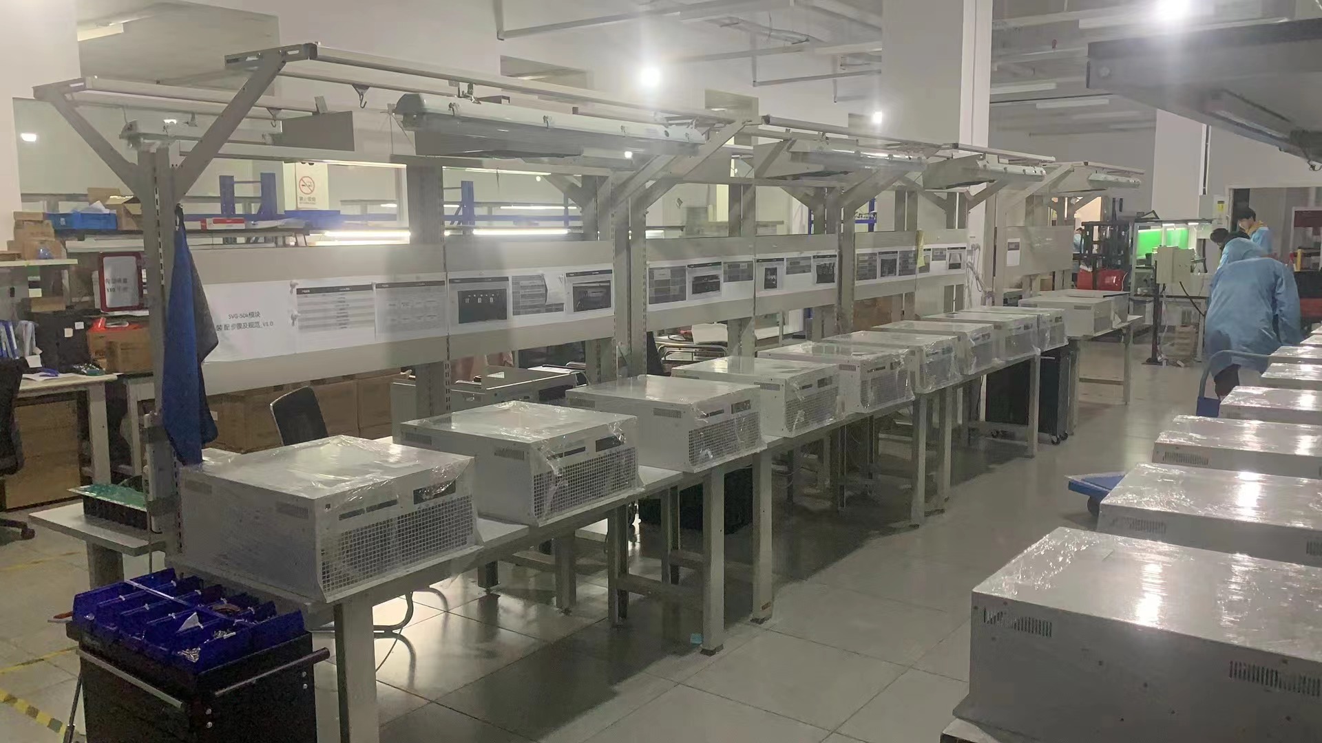
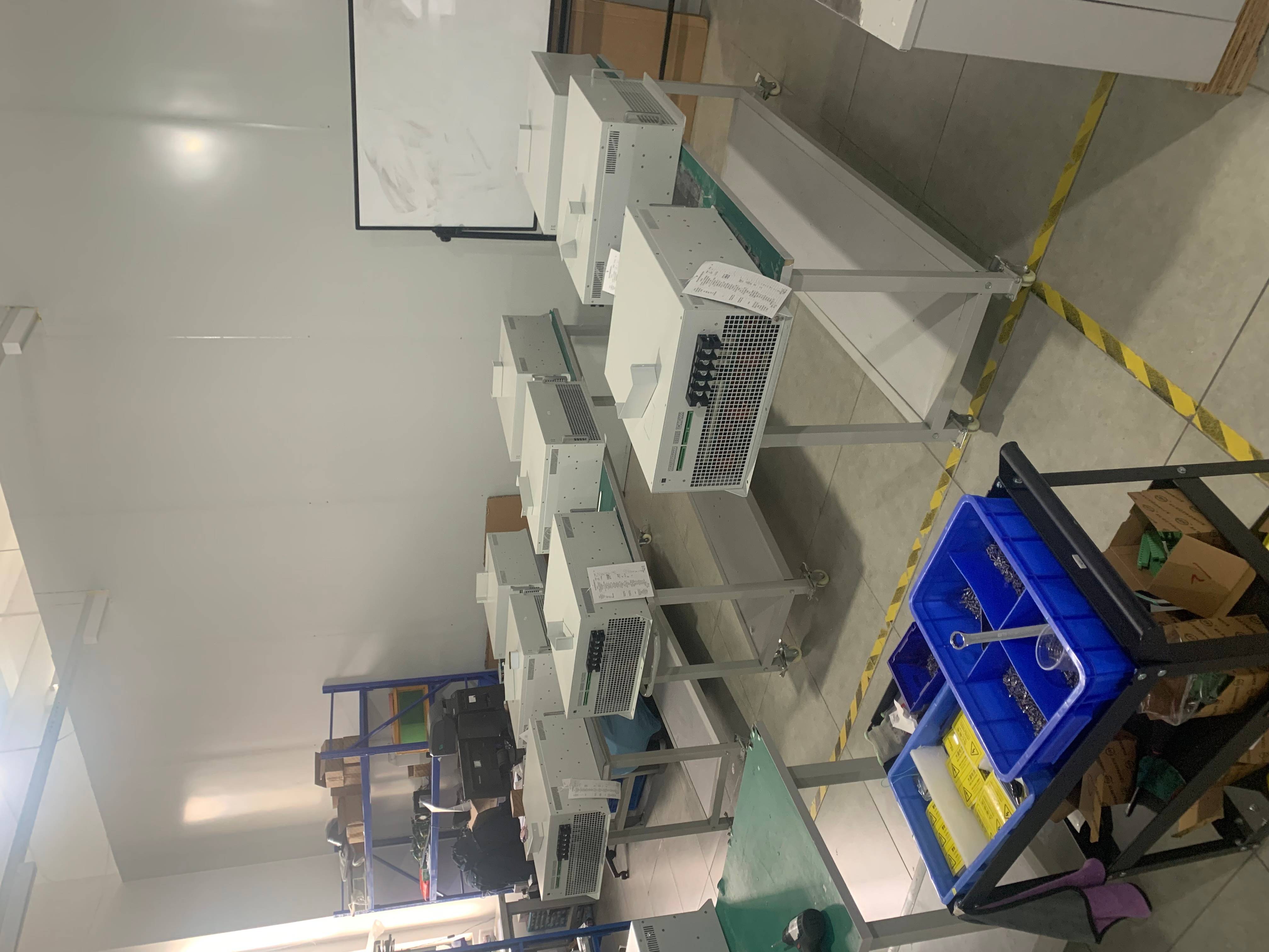
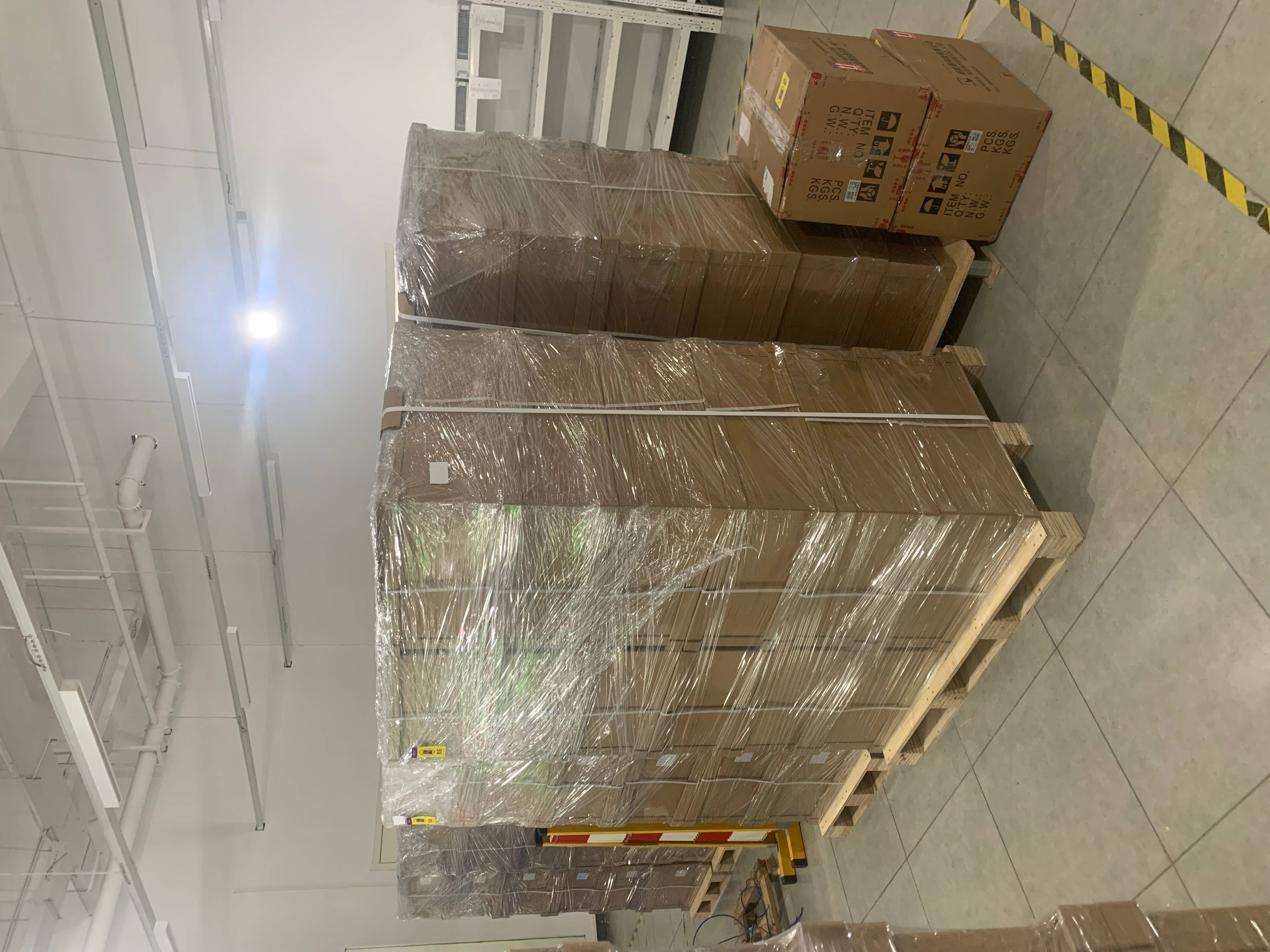
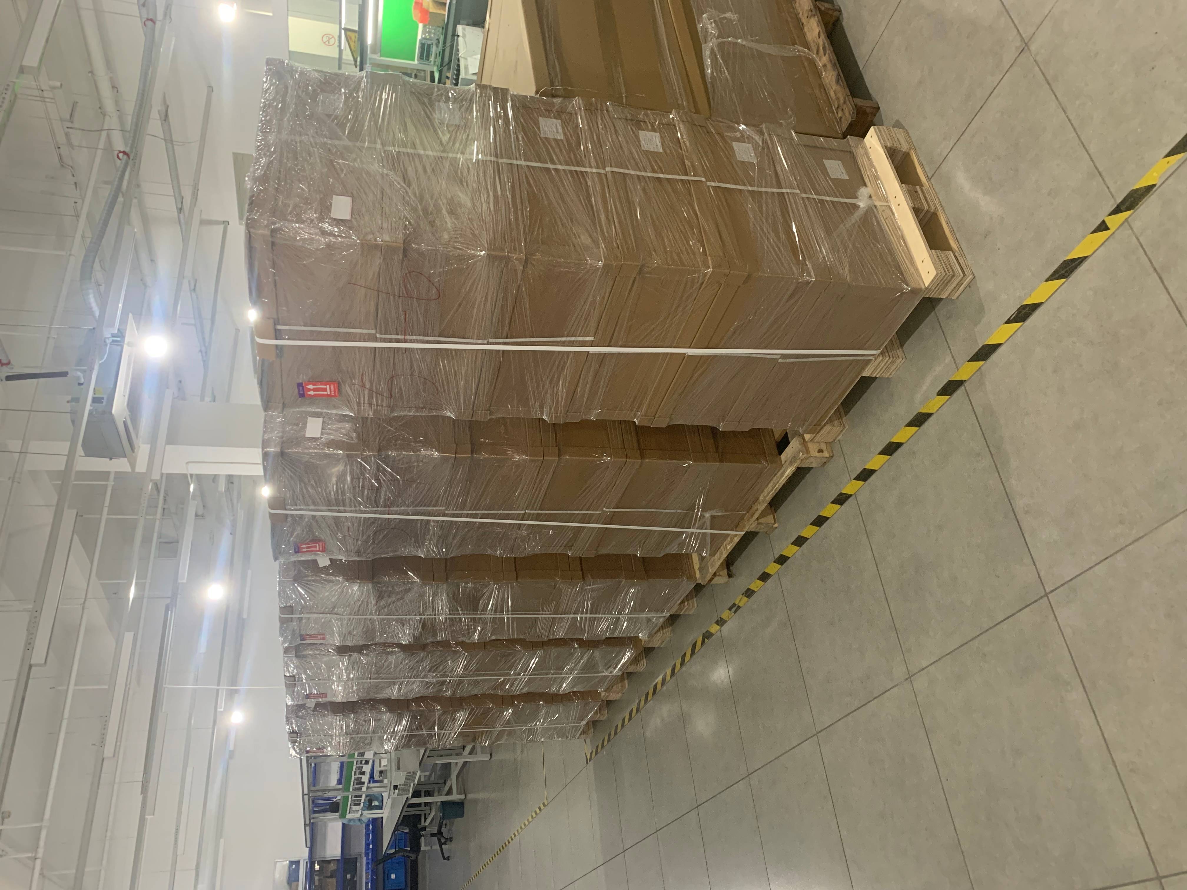
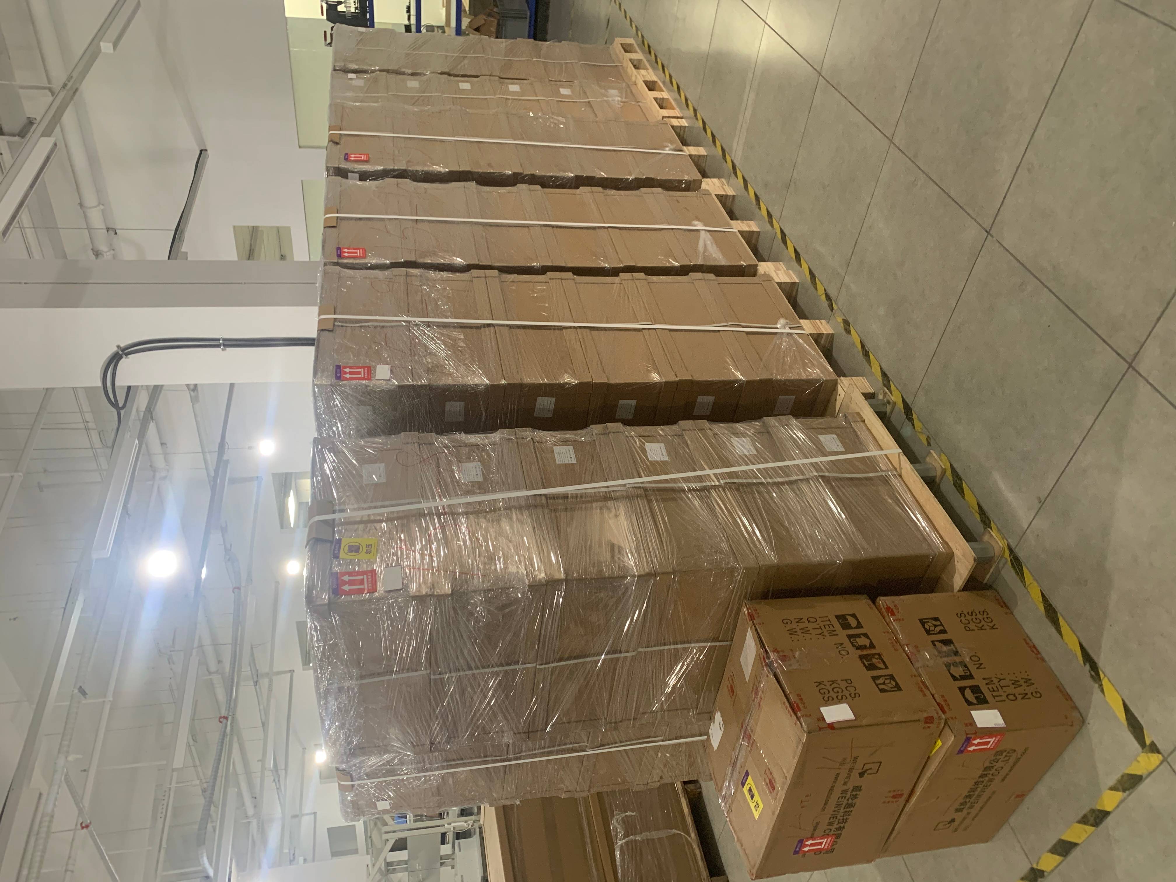
Product Packing
Frequently Asked Questions (FAQ)
Q1: How does a Static Var Generator (SVG) differ from standard capacitor banks?
Unlike traditional step-controlled capacitor banks, SVG provides continuous, stepless, and dynamic reactive power compensation. SVG operates as a controlled current source, preventing issues like over-compensation, under-compensation, or harmonic resonance.
Q2: What is the response time of the SVG?
The system features an ultra-fast response time of under 10ms (with step current response under 3ms), making it highly suitable for applications with rapidly fluctuating loads such as cranes, welding machines, and saw mills.
Q3: Can the SVG correct load imbalances?
Yes, the SVG is designed with current imbalance correction capabilities to balance loads across three phases effectively, which optimizes grid stability.
Q4: How does the SVG perform in systems with high harmonic distortion?
The SVG is unaffected by harmonic resonance and distortion. It can actively eliminate odd harmonics in the output current using multilevel/cascade technology, maintaining output current harmonic levels below 2.5%.
Q5: What happens during grid voltage drops?
The SVG remains unaffected by network voltage drops. It continues providing the necessary full reactive current compensation even under reduced grid voltage levels to ensure stable working conditions.
Q6: How many SVG modules can be connected in parallel?
There is no strict limitation on parallel connections. A single centralized monitoring module can support and control up to 8 power modules simultaneously to scale up the system output.