DC-DC 9A 300W Buck Converter 5-40V to 12-35V Power Module 12A Model 0123 None

Product Description

68.8 g
Module Weight
XL4016
Main Chip Model
QS-2405CCBD-12A
Power Module Model
65 × 47 × 23.5 mm
Dimensions (L × W × H)
Friendly Reminder & Current Updates:

In stock specifications: The maximum current is 8–9 A, the maximum input voltage is 40 V, and the maximum output voltage is around 35 V.

Due to the 12A current-chip manufacturer ceasing production, the replacement chip’s current rating has been reduced from the previous 12 A to 8 A (the maximum current measured in actual tests is around 9 A). The input voltage has changed from the previous 32 V to 40 V, and the output voltage has changed from the previous 28 V to 35 V. It can supply power to 10 strings of high-power LEDs. We will provide further notice upon arrival of the 12A chip.

Typical Applications

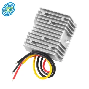
Adjustable power supplies (with a robust 12 A rating), high-power LED drivers, LED display drivers, lead-acid battery chargers, lithium-battery chargers, automotive power supplies, in-vehicle laptop power adapters (step-down), regulated power supplies, and low-voltage system power supplies—for example, stepping down a 12 V battery to 6 V for children’s toy cars—as well as 24 V to 12 V at 12 A, 12 V to 5 V at 12 A, 24 V to 5 V at 12 A, 24 V to 19 V/20 V, and more—making these solutions applicable across an extremely wide range of applications.

Product Features
1

The constant turn-light current is set to 0.1 times the constant-current value (used during charging to determine whether the battery is fully charged).

2

A dedicated reference IC and high-precision sampling resistor are used to ensure more stable constant-current operation (with a temperature drift of less than 5% when maintaining a constant current of 5 A over the temperature range of 20°C to 60°C). Especially suitable for LED drivers.

3

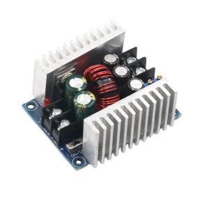
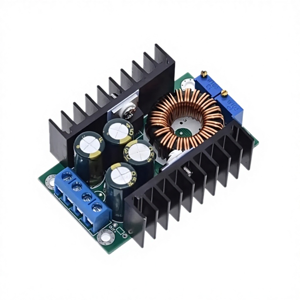
High output current: the maximum output current can reach 12 A, meeting the needs of most applications.

4

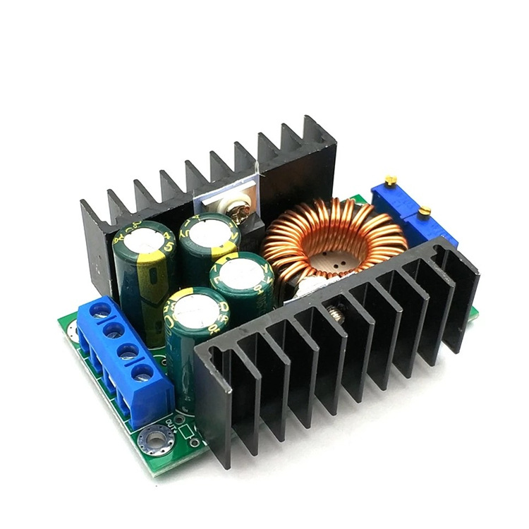
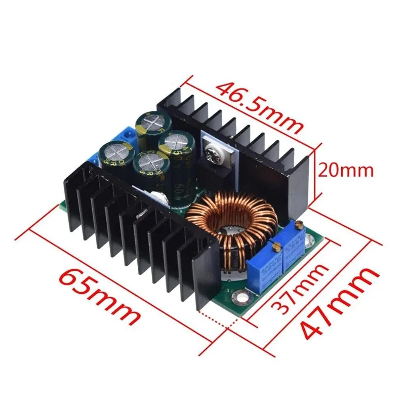
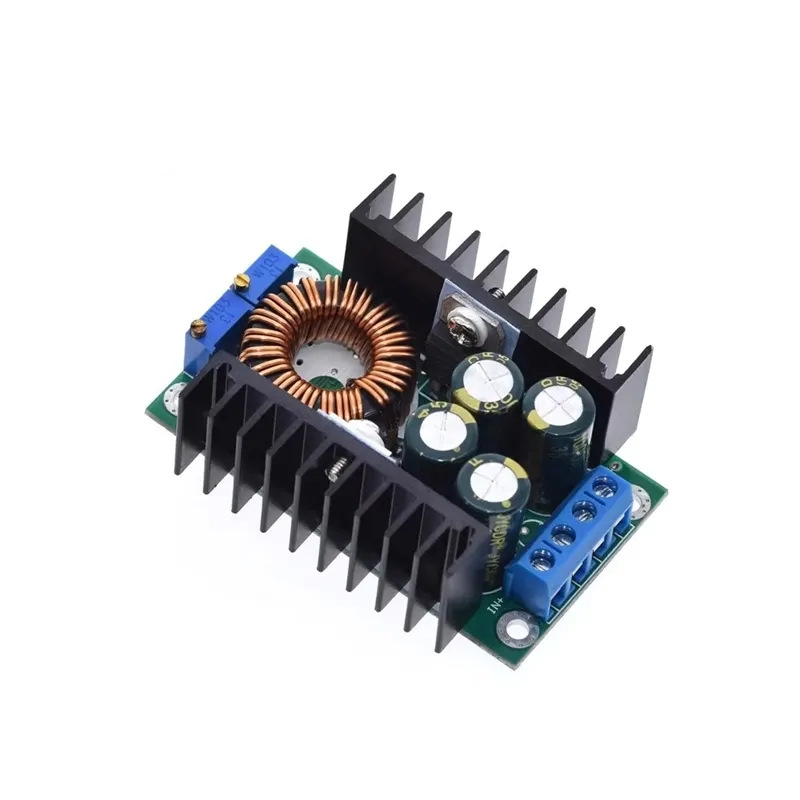
Four high-frequency capacitors effectively reduce output ripple and enhance operational stability.

5

Dual heat-sink design: separate heat sinks for the MOSFET and the Schottky diode, ensuring excellent thermal performance without mutual interference.

6

Employ large-size iron-silicon-aluminum magnetic cores at any cost to enhance operational efficiency, and use pure copper bifilar winding to reduce heat generation and further improve efficiency.

7

3296 multi-turn potentiometer with high voltage and current adjustment accuracy and excellent stability.

8

Dedicated current-sensing shunt resistor: high measurement accuracy, excellent stability, and low temperature drift. Essential for LEDs.

9

Dual-color indicator light for clear status visualization. Essential for charging.

10

Both voltage and current are adjustable, making it an excellent adjustable power supply; the 12A current rating provides ample power.

Module Parameters
Module Nature Non-isolated buck constant-current/constant-voltage module (CC/CV) charging module
Scope of Application High-power LED constant-current drive, lithium-battery charging (including ferroelectric), 4V/6V/12V/14V/24V lead-acid charging, Ni-Cd/Ni-MH charging, solar panels, and wind turbines.
Input Voltage 7-32V (without constant current, 5–32 V)
Output Voltage Continuously adjustable (0.8-28V) / Fixed output choice (0.8-28V for bulk orders; samples are shipped as adjustable models). If you require higher voltage, please contact me directly.
Output Current Maximum 12 A (if power transistor temp exceeds 65°C, add fan; for 24 V to 12 V conversion up to 6 A, fan is generally not required in open air).
Constant Current Range 0.2–12 A (adjustable) (Without constant current, this function is not available).
Turn Current Constant current value * 0.1 (Used to indicate charging completion. E.g., if constant current is 3 A, lamp switches at 0.3 A; if constant current is 2 A, lamp switches at 0.2 A. The actual value is approximate).
Minimum Pressure Differential 1V
Output Power Maximum approx 300 W (if transistor temp exceeds 65°C, please add a fan).
Conversion Efficiency Up to approximately 95% (efficiency increases as output voltage rises).
Operating Frequency 300 kHz
Output Ripple Input 24 V, Output 12 V 5 A: approx 50 mV (20 Mbps bandwidth, noise excluded, for reference only).
Operating Temperature Industrial-grade (-40°C to +85°C). Monitor transistor temp and enhance cooling if too high.
No-load Current Typical 20 mA (24 V to 12 V)
Regulation Accuracy Load regulation: ±1% (constant pressure); Voltage regulation: ±1%
Constant-current Accuracy Constant current variations <5% when temperature changes from 25°C to 60°C (at 5 A setting).
Dynamic Response Speed 5% 200 µs
Potentiometer Direction Clockwise (increase), counterclockwise (decrease). Potentiometer closer to input is for CV; closer to output is for CC.
Indicator Light Two-color. Charging: red; Complete/No-load: green. Models without CC control: always red.
Module Protections Output short-circuit: Yes (constant current limit); Input reverse polarity: None; Output backflow prevention: None.
Wiring Method Terminal block
Usage Instructions
Battery Charging Mode
  1. Determine the float charge voltage and charge current required for the rechargeable battery, as well as the module’s input voltage.
  2. Adjust the constant-voltage potentiometer to set the output voltage to approximately 5 V.
  3. Use the 10 A current range of a multimeter to measure the short-circuit output current, while simultaneously adjusting the constant-current potentiometer to set the output current to the specified charging current value.
  4. Adjust the constant-voltage potentiometer to set the output voltage to the float charge voltage.
  5. Connect the battery and perform a test charge.
Important: Steps 1, 2, 3, and 4 involve connecting the module’s input to the power supply while leaving the output open-circuited and disconnected from the battery.
LED Constant-Current Driver Mode
  1. Determine the LED’s operating current and maximum operating voltage.
  2. Adjust the constant-voltage potentiometer to set the output voltage to approximately 5 V.
  3. Use the 10 A current range on a multimeter to measure the output short-circuit current, while simultaneously adjusting the constant-current potentiometer to set the output current to the specified LED operating current.
  4. Adjust the constant-voltage potentiometer to set the output voltage to the LED’s maximum operating voltage.
  5. Connect the LED and perform a test run.
Important: Steps 1, 2, 3, and 4 involve connecting the module’s input to the power supply while leaving the output open-circuited and without any LED lights connected.
DC-DC Buck Converter 300W 12A Power Module Detail Image 1
DC-DC Buck Converter 300W 12A Power Module Detail Image 2
DC-DC Buck Converter 300W 12A Power Module Detail Image 3
Specification Table
Item Value
Functional Application DC-DC buck converter
Brand Name Other
Model Number 0123
Frequently Asked Questions (FAQ)
Q What is the main chip of this buck converter?

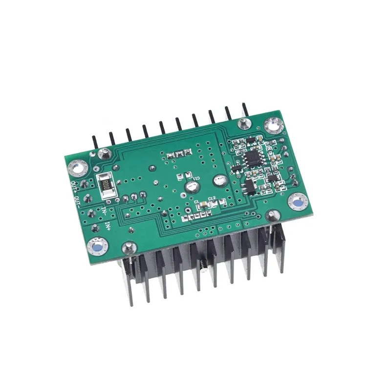
The main chip currently used in this power supply module is the XL4016.

Q Why has the current limit changed from 12A to 8-9A?

The 12A current-chip manufacturer has ceased production. The replacement chip has a reduced continuous current rating of 8A (measured up to 9A in actual tests), but benefits from an increased input voltage capability of 40V and output capability of 35V.

Q When do I need to use an external cooling fan?

An active cooling fan is required if the power transistor temperature exceeds 65°C, or when operating at sustained output currents above 6A in enclosed or high-ambient-temperature environments.

Q Does this module support constant current (CC) and constant voltage (CV) adjustment?

Yes. It features dual independent potentiometers that allow you to set both the output voltage (CV) and current limits (CC) for charging batteries or driving LEDs safely.

Q Is there reverse polarity or backflow protection built into this module?

No, there is no built-in input reverse polarity protection or output backflow prevention. For battery charging, it is highly recommended to install external blocking diodes to prevent damage to the module.

Related Products